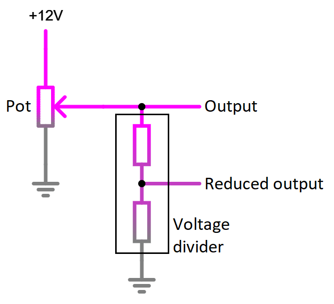
Don't use voltage dividers
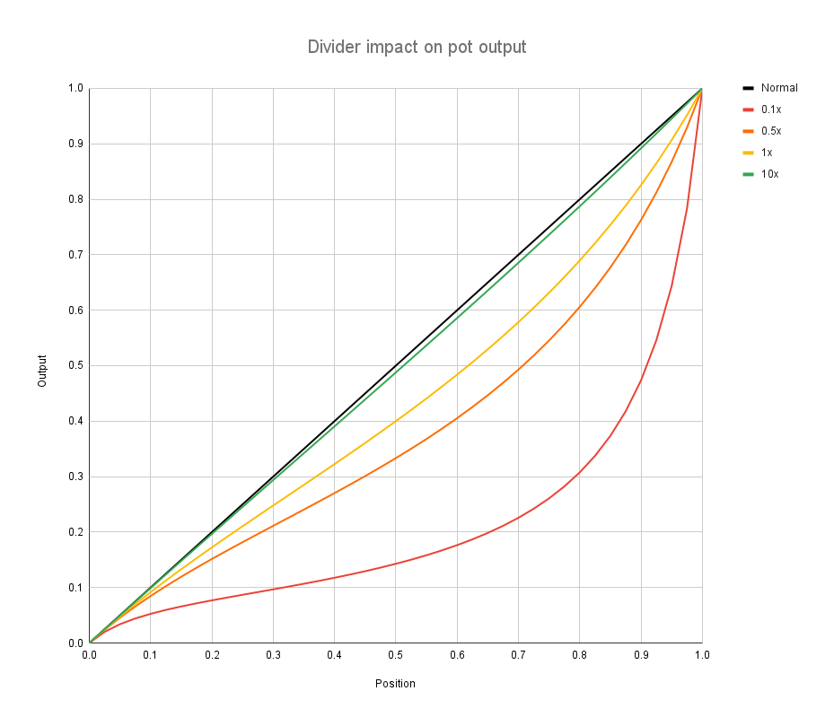
This is how a voltage divider will skew the output signal of potentiometer. If you must do it, then use divider with total resistance that is at least 20 times larger that potentiometer resistance, to avoid impacting it's output.
Exactly the same thing applies to sensors that use pull-up resistor, like NTP based temperature sensors. For those relationship between divider total resistance and sensor normal output will be a bit more complicated, but similar. Device that reads the sensor, will always read smaller voltage than that if divider wasn't present. So use voltage dividers with care, and use large resistance values.
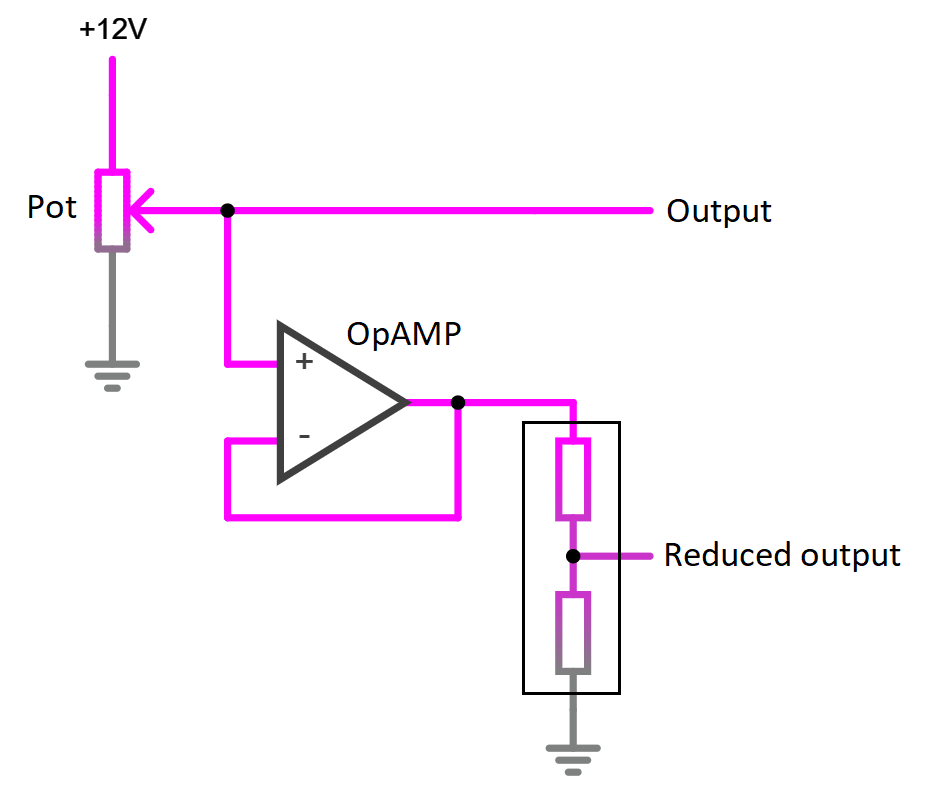
But large resistance values create high impedance circuit, that is more susceptible to noise. What is the solution ? Use OpAMP. Those have high impedance input, and low impedance output. Meaning that they won't affect original signal in meaningful way, and output can have low resistance voltage divider, to avoid being susceptible to noise.
But this isn't perfect solution either, as this works only if potentiometer supply is known and constant voltage. Because this way you are measuring voltage of potentiometer output, but in reality with potentiometers we don't care about their absolute output voltage, but rather ratio between supply and output. So you can see that if we don't know supply voltage, then this voltage measurement of potentiometer output is useless. One way around is to just measure both voltages and do maths calculation to find this ration. Other way is to use elaborate circuit that converts voltage into PWM signal, where duty cycle is directly proportional to this ration between potentiometer output and it's supply voltage. Then it can be converted back to analogue voltage, keeping the same ration between new supply voltage and signal.