Relay PDM series
Relay logic Power Distribution Modules.
Simple firmware-less PDMs that can be configured using resistors and diodes.
rPDM-1
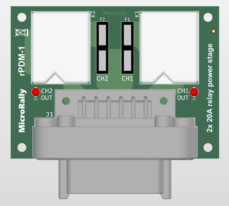
2 channel 20A relay power stage. Channels can be either independent or staged - second output can be activated only if first output is on and not fused. Useful for protecting main pump, mandating that lift pump is active or in case of failure of lift pump.
Pinout
Connector - TE Connectivity DT series, 12pins
PCB header part# - DT13-12Px (x - key)
Amperage - 13A/pin
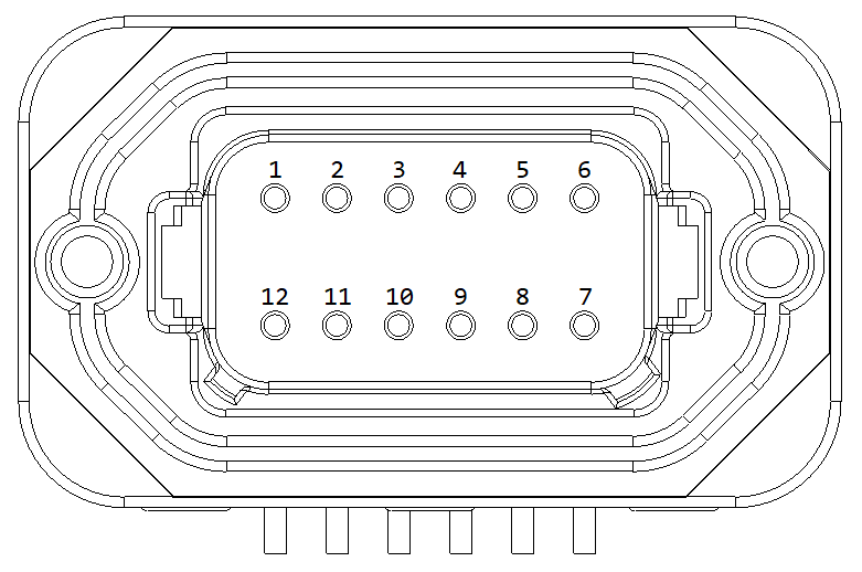
| Pin# | Signal | Description | Type |
|---|---|---|---|
| 1 | CH2_OUT | Output 2 | PO |
| 2 | CH2_CTRL | Control 2 | DIN |
| 3 | VBAT | Battery power | P |
| 4 | VBAT | Battery power | P |
| 5 | CH1_CTRL | Control 1 | DIN |
| 6 | CH1_OUT | Output 1 | PO |
| 7 | CH1_OUT | Output 1 | PO |
| 8 | GND | Ground | G |
| 9 | VBAT | Battery power | P |
| 10 | VBAT | Battery power | P |
| 11 | VIGN | Enable power | P |
| 12 | CH2_COUT | Output 2 | PO |
P - Power input, 12V
G - Ground, 0V
PO - Power output, 12V, High side switching
DIN - Digital input, 12V, active low
Enable power input load is two relay coils, each 90 Ohms. That means that switch that controls relays must be rated for at least 0.15A current. Same applies for enable power source, it has to able to provide 0.30A of current.
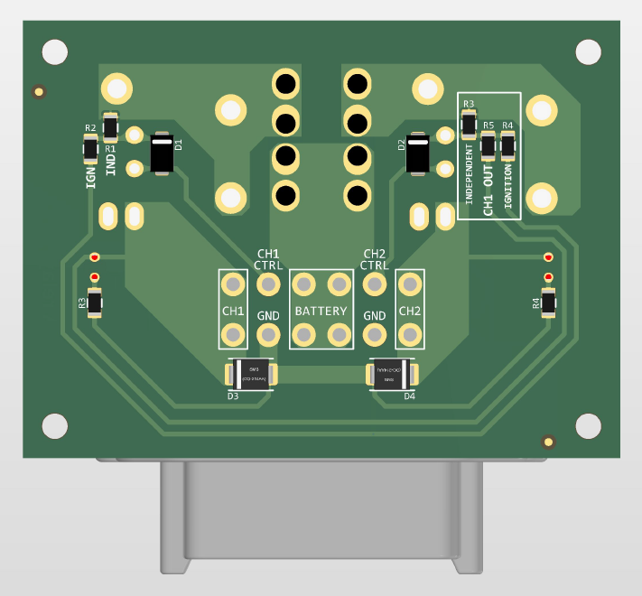
Configuration options
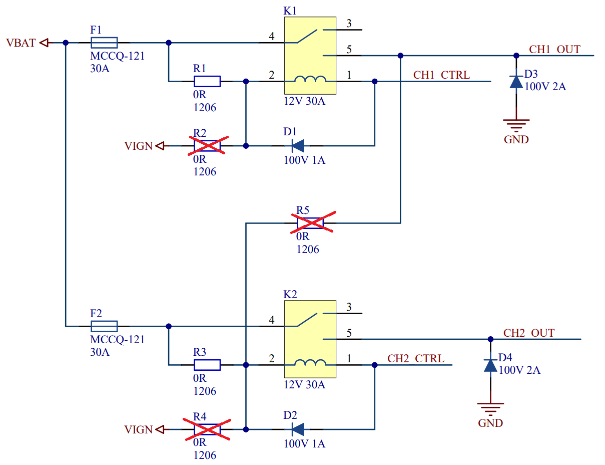
Two independent, always available channels. Relay enable source is same as main power source.

Two independent, "ignition" enabled channels. Relay enable source is different from main power source. That doesn't have to be necessary ignition, it can be any 12V power rail, that can be used as enable signal.
Also it is allowed to have mixed enable sources. One can be battery enabled while other can be ignition enabled.
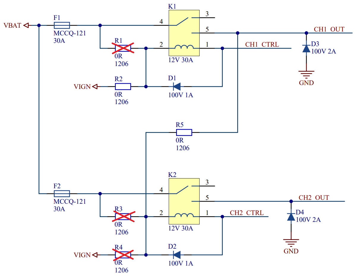
Dependent or staged channels. Choose enable source of first channel. Second channels enabled source is first channels output. For lift and main pump setup connect lift pump to CH1 and main pump to CH2.
Typical connections
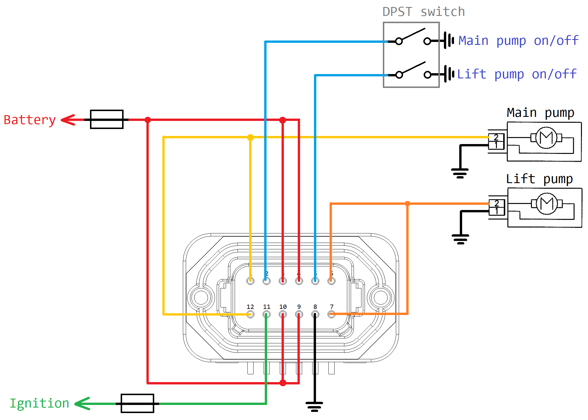
Example of stage fuel pump setup.
rPDM-2
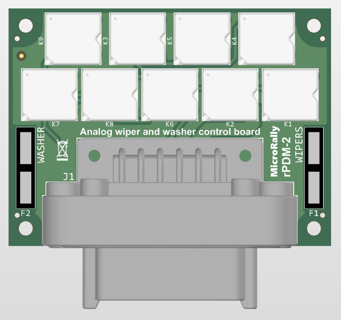
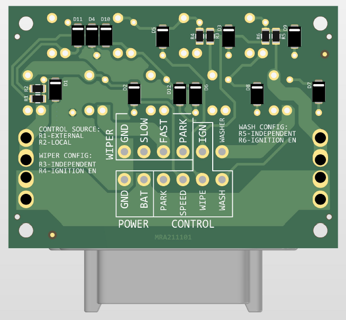
Relay based, analog wiper and washer control board.
Pinout
Connector - TE Connectivity DT series, 12pins
PCB header part# - DT13-12Px (x - key)
Amperage - 13A/pin
| Pin# | Signal | Description | Type |
|---|---|---|---|
| 1 | WASH_PWR | Washer pump output | PO |
| 2 | VIGN | Enable power | P |
| 3 | PARK_SW | Wiper park switch | DIN |
| 4 | PWR_HIGH | Wiper fast winding output | PO |
| 5 | PWM_LOW | Wiper slow winding output | PO |
| 6 | GND | Ground | G |
| 7 | GND | Ground | G |
| 8 | VBAT | Battery power | P |
| 9 | PARK_SW | Wiper park switch | DIN |
| 10 | WIPER_SPEED | Wiper speed select switch | DIN |
| 11 | WIPE_SW | Wiper on/off switch | DIN |
| 12 | WASH_SW | Washer on/off switch | DIN |
P - Power input, 12V
G - Ground, 0V
PO - Power output, 12V, High side switching
DIN - Digital input, 12V, active low
Operation
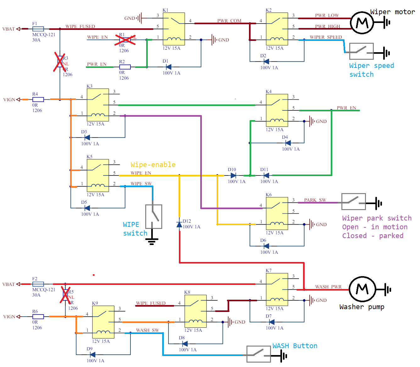
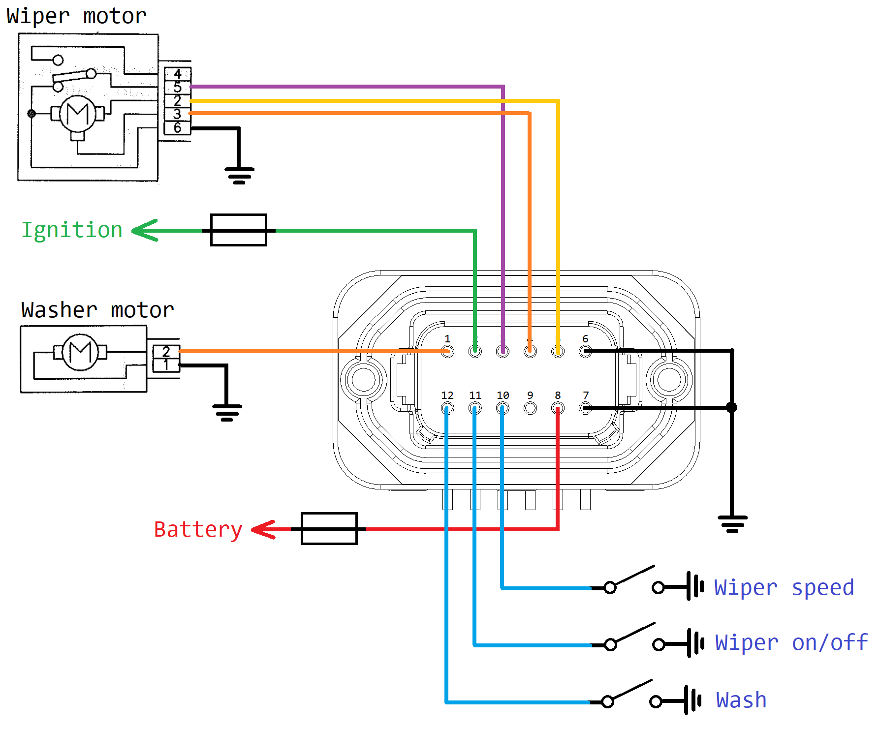
This is recommended schematic. This way relays can drain power only while enable power (ignition) is on. This schematic uses park switch input, so that wipers return to home position even if wipers have been turn off. Just like in OEM implementation.
K1 relay provides main power enable and breaking functionality. When wipers are turned off and parked, then motor supply side is connected to ground to rapidly stop wiper motor. Power is enabled while PWR_EN signal is active. Refer to further description for its logic.
K2 relay is used for wiper speed select. This works only with wiper motors that have two windings - fast and slow. Most OEM ones do. Switch connected to WIPER_SPEED signal controls it.
K3, K4, K5 and K6 relays make main wiper logic control. When Wipe switch is activated, then K5 turns on and provides power to K4 and K6 relays. K6 disconnects park switch and K4 keeps wipers powered until wiper switch is off (K5 turned off) and park switch is closed, indicating home position.
K7, K8, K9 provide Washer pump supply and logic. When washer pump is activated, then also wiper circuit is activated. Providing at least one wipe cycle. If wiper power fuse is blown, then washer is also disabled. This logic is done using K8 relay. K9 is main washer enable relay and K7 is washer power relay.
Typical connections
Ignition supply considerations
There are total of 9 relays, of which 7 are ignition supplied. Each relay coil is 254 ohms. That means single relay requires 50mA current. That is also the minimum current requirement for switches. Total load on ignition is 0.35A
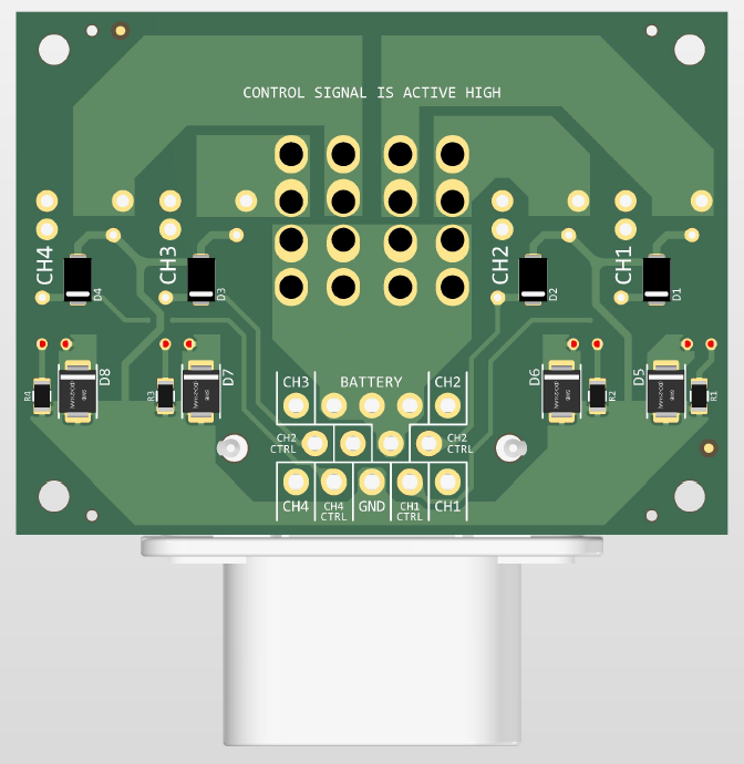
rPDM-3
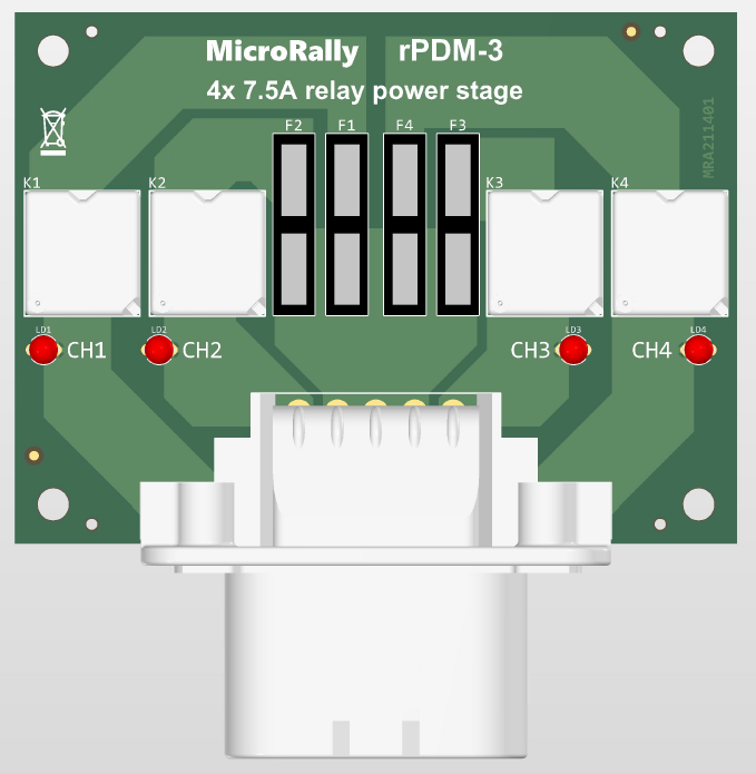
4 channel 7.5A relay power stage. All channels are independently controlled, also all channels have configurable enable source - either battery or "ignition". All relays have flyback diodes, to protect against voltage spikes during turning off. Each output has it's own fuse and output indicator.
Pinout
Connector - TE Connectivity Ampseal series, 14pins
PCB header part# - 776266-x (x - key)
Amperage - 7.5A/pin
| Pin# | Signal | Description | Type |
|---|---|---|---|
| 1 | CH2_OUT | Output 2 | PO |
| 2 | VBAT | Battery power | P |
| 3 | VBAT | Battery power | P |
| 4 | VBAT | Battery power | P |
| 5 | CH3_OUT | Output 3 | PO |
| 6 | CH2_CTRL | Input 2 | DIN |
| 7 | VBAT | Battery power | P |
| 8 | VIGN | Enable power | P |
| 9 | CH3_CTRL | Input 3 | DIN |
| 10 | CH1_OUT | Output 1 | PO |
| 11 | CH1_CTRL | Input 1 | DIN |
| 12 | GND | Ground | G |
| 13 | CH4_CTRL | Input 4 | DIN |
| 14 | CH4_OUT | Output 4 | PO |
P - Power input, 12V
G - Ground, 0V
PO - Power output, 12V, High side switching
DIN - Digital input, 12V, active low
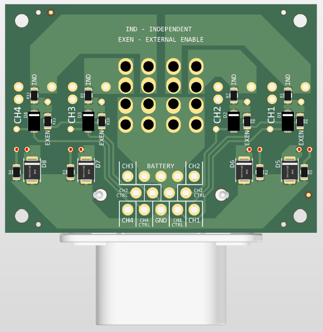
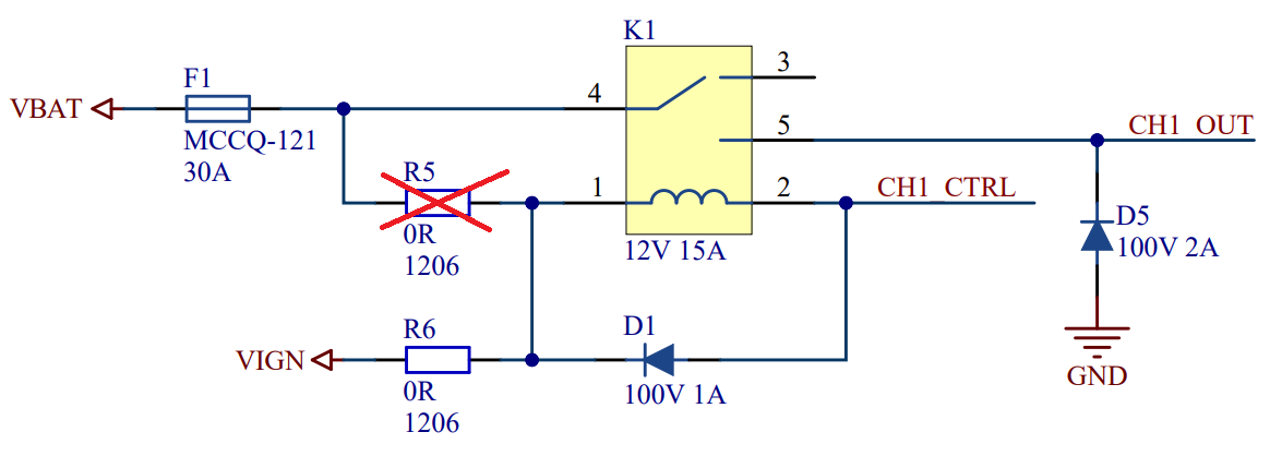
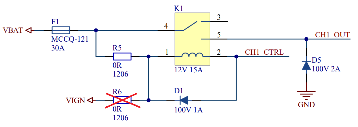
Configuration options
There are 4 identical, independent channels. Each has its own output and control. Each channel can be either Battery or "Ignition" power enabled. This is chosen with resistors. Bellow are both possible configurations. Each channel can have its configuration. Mind that VIGN is shared among all channels.
rPDM-4
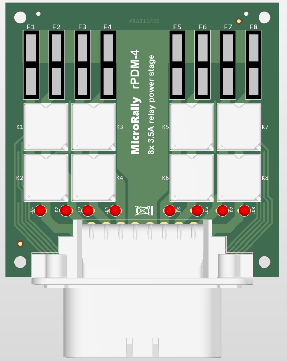
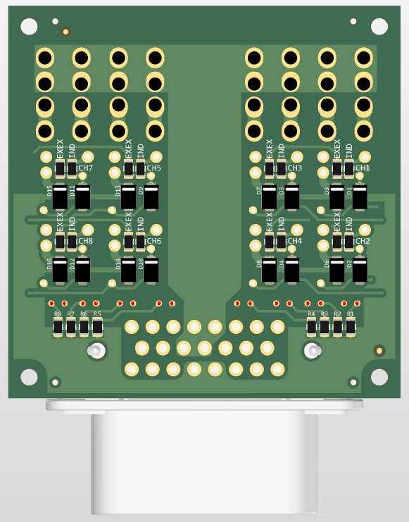
8x 3.5A channel relay power stage. Same as rPDM-3, but with more, lower current channels.
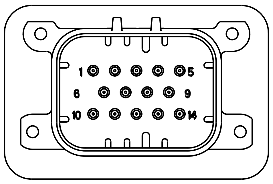
Pinout
Connector - TE Connectivity Ampseal series, 23pins
PCB header part# - 770669-x (x - key)
Amperage - 7.5A/pin
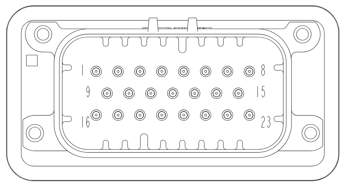
| Pin# | Signal | Description | Type |
|---|---|---|---|
| 1 | CH2_OUT | Output 2 | PO |
| 2 | CH3_OUT | Output 3 | PO |
| 3 | CH4_OUT | Output 4 | PO |
| 4 | VBAT | Battery power | P |
| 5 | VBAT | Battery power | P |
| 6 | CH5_OUT | Output 5 | PO |
| 7 | CH6_OUT | Output 6 | PO |
| 8 | CH7_OUT | Output 7 | PO |
| 9 | CH1_OUT | Output 1 | PO |
| 10 | CH1_CTRL | Input 1 | PO |
| 11 | VIGN | Enable power | P |
| 12 | VBAT | Battery power | P |
| 13 | VBAT | Battery power | P |
| 14 | CH8_CTRL | Input 8 | DIN |
| 15 | CH8_OUT | Output 8 | PO |
| 16 | CH2_CTRL | Input 2 | DIN |
| 17 | CH3_CTRL | Input 3 | DIN |
| 18 | CH4_CTRL | Input 4 | DIN |
| 19 | GND | Ground | G |
| 20 | GND | Ground | G |
| 21 | CH5_CTRL | Input 5 | DIN |
| 22 | CH6_CTRL | Input 6 | DIN |
| 23 | CH7_CTRL | Input 7 | DIN |
P - Power input, 12V
G - Ground, 0V
PO - Power output, 12V, High side switching
DIN - Digital input, 12V, active low
rPDM-5
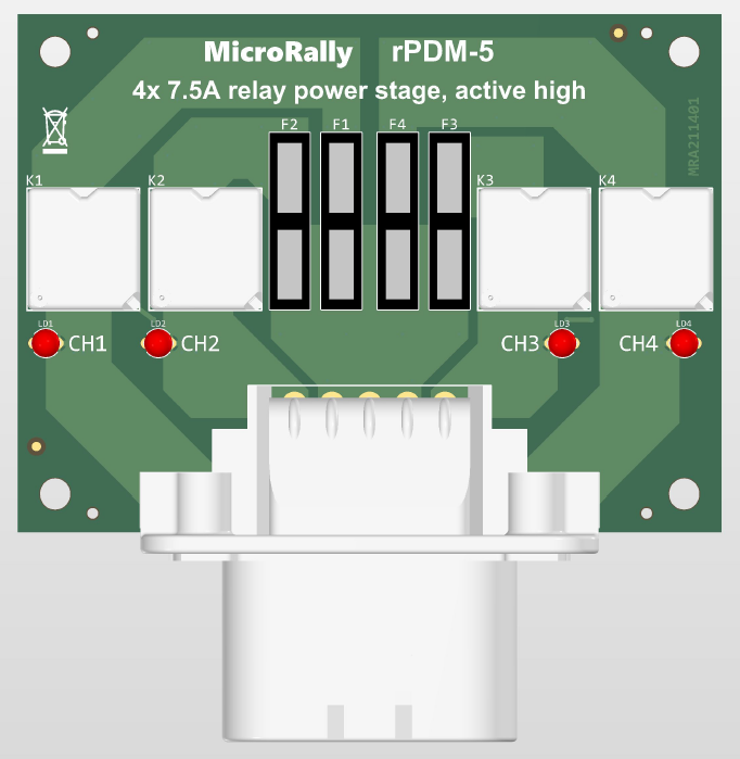
4x 7.5A channel relay power stage, with active high control
Pinout
Connector - TE Connectivity Ampseal series, 14pins
PCB header part# - 776266-x (x - key)
Amperage - 7.5A/pin
| Pin# | Signal | Description | Type |
|---|---|---|---|
| 1 | CH2_OUT | Output 2 | PO |
| 2 | VBAT | Battery power | P |
| 3 | VBAT | Battery power | P |
| 4 | VBAT | Battery power | P |
| 5 | CH3_OUT | Output 3 | PO |
| 6 | CH2_CTRL | Input 2 | DIN |
| 7 | VBAT | Battery power | P |
| 8 | - | Not connected | - |
| 9 | CH3_CTRL | Input 3 | DIN |
| 10 | CH1_OUT | Output 1 | PO |
| 11 | CH1_CTRL | Input 1 | DIN |
| 12 | GND | Ground | G |
| 13 | CH4_CTRL | Input 4 | DIN |
| 14 | CH4_OUT | Output 4 | PO |
P - Power input, 12V
G - Ground, 0V
PO - Power output, 12V, High side switching
DIN - Digital input, 12V, active high
Operation
Each channel consists of a single relay. Relay coil one end is permanently connected to the ground, and other is user defined input. Input is active high, 12V signal, capable to source at least 50mA current. There are no configuration options or common enabled sources.
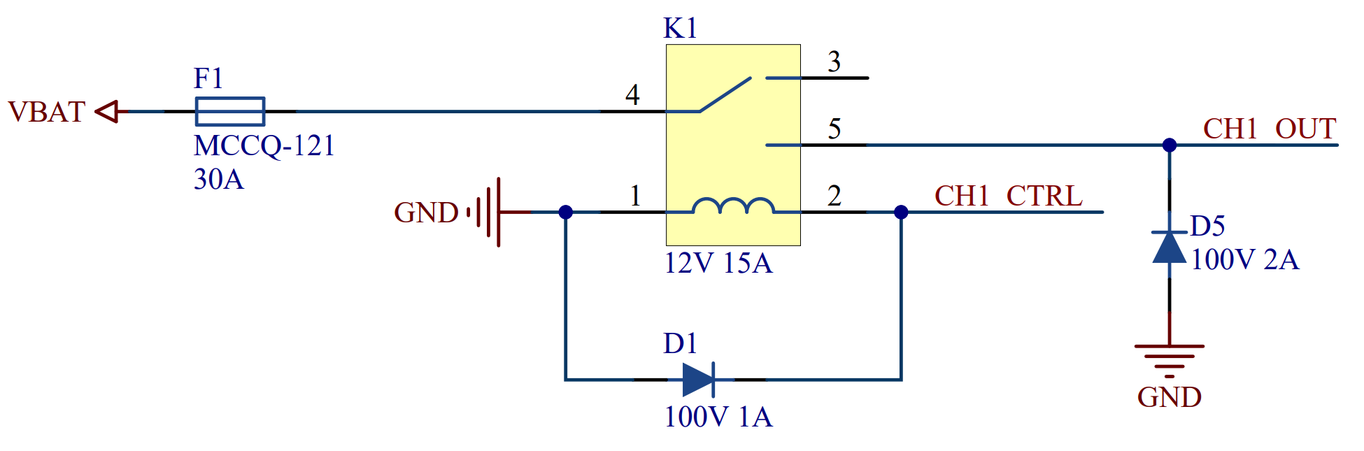
rPDM-6
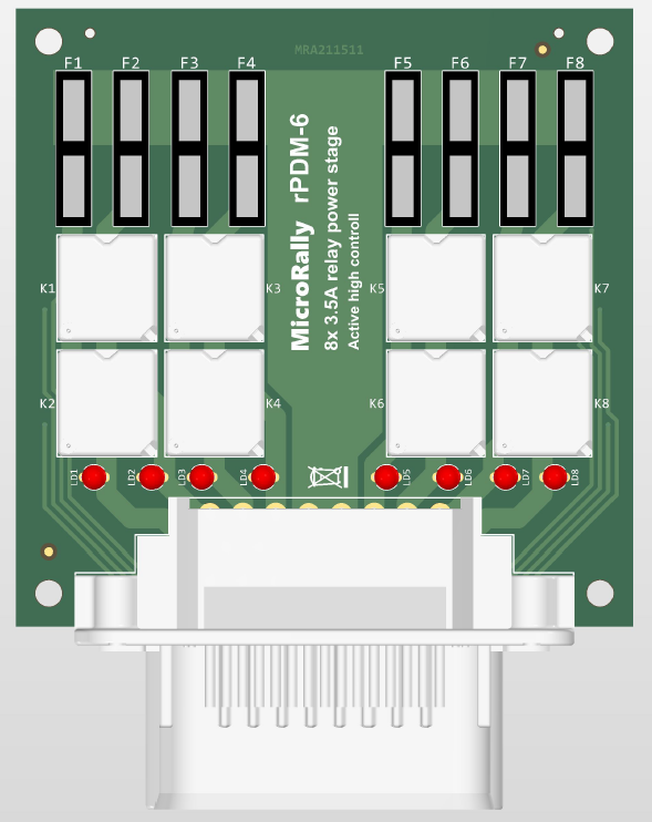
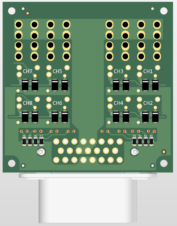
8x 3.5A channel relay power stage. Same as rPDM-5, but with more, lower current channels.
Pinout
Connector - TE Connectivity Ampseal series, 23pins
PCB header part# - 770669-x (x - key)
Amperage - 7.5A/pin
| Pin# | Signal | Description | Type |
|---|---|---|---|
| 1 | CH2_OUT | Output 2 | PO |
| 2 | CH3_OUT | Output 3 | PO |
| 3 | CH4_OUT | Output 4 | PO |
| 4 | VBAT | Battery power | P |
| 5 | VBAT | Battery power | P |
| 6 | CH5_OUT | Output 5 | PO |
| 7 | CH6_OUT | Output 6 | PO |
| 8 | CH7_OUT | Output 7 | PO |
| 9 | CH1_OUT | Output 1 | PO |
| 10 | CH1_CTRL | Input 1 | PO |
| 11 | - | Not connected | - |
| 12 | VBAT | Battery power | P |
| 13 | VBAT | Battery power | P |
| 14 | CH8_CTRL | Input 8 | DIN |
| 15 | CH8_OUT | Output 8 | PO |
| 16 | CH2_CTRL | Input 2 | DIN |
| 17 | CH3_CTRL | Input 3 | DIN |
| 18 | CH4_CTRL | Input 4 | DIN |
| 19 | GND | Ground | G |
| 20 | GND | Ground | G |
| 21 | CH5_CTRL | Input 5 | DIN |
| 22 | CH6_CTRL | Input 6 | DIN |
| 23 | CH7_CTRL | Input 7 | DIN |
P - Power input, 12V
G - Ground, 0V
PO - Power output, 12V, High side switching
DIN - Digital input, 12V, active high