uDCCD controller
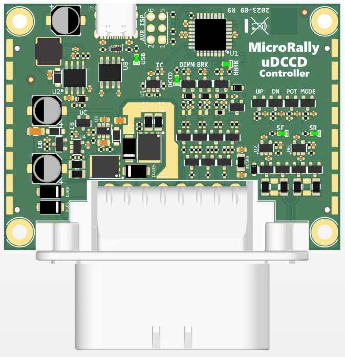
Simple, but capable DCCD controller. No need for mandatory ABS inputs or CAN bus dependencies. But more than just dumb PWM generator. Controller has closed loop current control. User settable lock level, either with potentiometer (thumb wheel) or buttons (like Si-Drive). Has inputs handbrake and brake signals for lock force override. Compatible with OEM instrument panel LEDs. Has the same 6 indicator light outputs with dim option.
Pinout
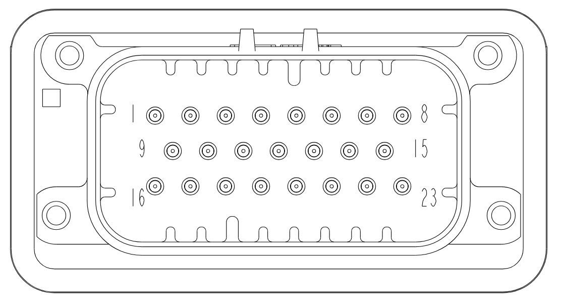
| Pin# | Signal | Description (uDCCD usage) | Type |
|---|---|---|---|
| 1 | VBAT | Coil power supply | P |
| 2 | OUTH | Coil switching supply | PO |
| 3 | OUTL | Coil return | PO |
| 4 | GND | Power ground | G |
| 5 | OD2 | Display 20% output | OD |
| 6 | OD4 | Display 60% output | OD |
| 7 | OD6 | Display 100% output | OD |
| 8 | 5V | 5V supply output | PO |
| 9 | IGN | Ignition power | P |
| 10 | FREQ1 | Front speed input | VR |
| 11 | FREQ2 | Rear speed input | VR |
| 12 | OD1 | Display 0% output | OD |
| 13 | OD3 | Display 40% output | OD |
| 14 | OD5 | Display 80% output | OD |
| 15 | DIN4 | Up (+) button input | DIN |
| 16 | GND | Logic power ground | G |
| 17 | HVDIN1 | Display dim input | HV DIN |
| 18 | HVDIN2 | Brakes signal input | HV DIN |
| 19 | HVDIN3 | Handbrake signal input | HV DIN |
| 20 | ADIN1 | Mode button input / Analog input | DIN, AIN |
| 21 | ADIN2 | Potentiometer input / TPS input | DIN, AIN |
| 22 | DIN3 | Down (-) button input | DIN |
| 23 | GND | Inputs ground | G |
P - Power supply, 12V
G - Ground, 0V
PO - Power output
OD - Open drain output, low side switching
AIN - Analog input, 5V
DIN - Digital input, 5V
HV DIN - High voltage digital input, 12V
VR - Variable reluctance or HALL speed input
Connections
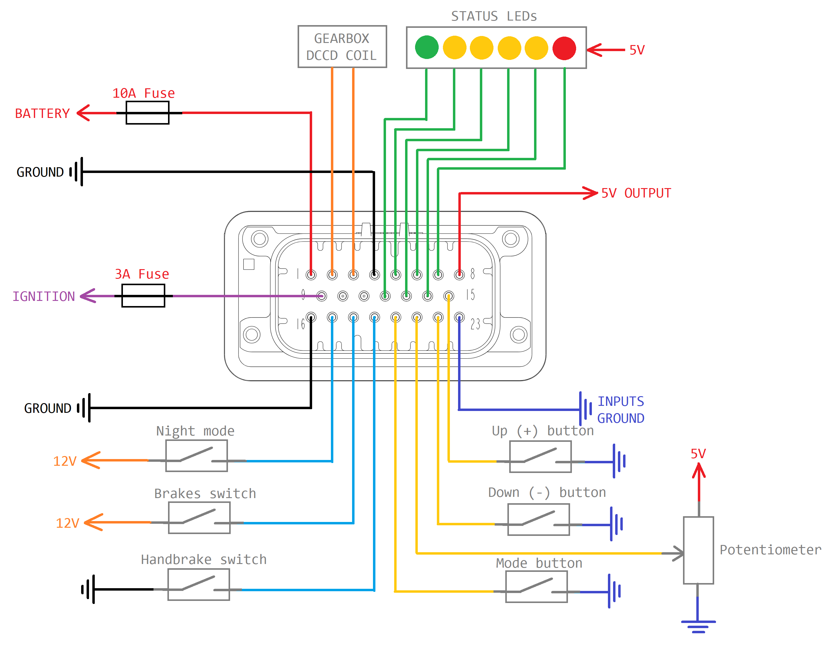
Typical connections.
Legacy versions
Documentation of old versions
Revison 7
Attiny88 based version with TE Ampseal 23 pin connector
User manual download
Interface cutout download
Revison 6
Attiny88 based version with Molex MiniFit connectors
User manual download
Interface cutout download